
found for ""
Mistakes to Avoid in Design & Operation of Reverse Osmosis Systems
By: G.K. Dhawan Ph.D., P.E., Applied Membranes, Inc.
Introduction
Reverse Osmosis technology is evolved into a widely used process for the purification of water. Well designed and properly operated systems give a trouble-free performance over long periods of time. Membranes in these systems have a long useful life. On the other hand mistakes made during the design or operation of reverse osmosis systems can lead to ongoing problems and reduced membrane life.
This article reviews some of the common mistakes made during the design and operation of the reverse osmosis systems.
Membrane Performance
There is one simple but extremely important fact in keeping the membranes at their peak performance: "Keep the membrane surface clean".
All impurities in water are removed at the membrane surface. The dynamics of this separation step must ensure that concentrated materials are not accumulating at the membrane surface. If concentrations are allowed to build up near the membrane, precipitation of low solubility substances will follow resulting in a decline in membrane performance.
Water Analysis
Understanding the water analysis and the potential problems caused by the sparingly soluble substances are crucial for the success of a reverse osmosis system. Many reverse osmosis systems have been designed and sold with no or incomplete water analysis. Some of these mistakes are difficult to fix in teh field and may even require discarding the existing system and starting all over again.
Recovery
Recovery is defined as the ration of the permeate flow to feed flow.
% Recovery = (Permeate Flow ÷ Feed Flow) × 100
In residential systems the recovery is expressed in terms of ratio of brine flow to permeate flow. For example, the brine: permeate flow ration may be 5:1. This can be converted into recovery as follows:
Feed flow = Permeate Flow + Brine Flow
% Recovery = (Permeate Flow × 100) ÷ Feed Flow
or = 100 ÷ 6 = 16.7%
It is recommended that for most tap waters the recovery for each membrane be maintained between 10 to 15%. Operating membranes at higher than recommended recovery will result in fouling of the membrane surface.
Membrane Flux
All membranes have one common limitation. They can only produce a maximum flow of a certain maximum permeate flow for a given water. This limit is controlled by the quality of feed water and not by the make of the membrane. For example, a maximum permeate flow for most tap water applications is 25 gallons per square foot per day. When membranes are run at fluxes higher than this value, fouling takes place.
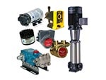
Feed Flow
A minimum feed flow must be maintained throughout the membrane. Feed velocity helps to reduce build up of concentrated materials at the membrane surface. When several membranes are being used, the arrangement of these membranes is crucial in maintaining proper flow velocities. This arrangement must be checked against other related factors such as higher pumping costs, recycle flow, etc.
System Shut-Down
Fouling tendency of feed water when flowing through membranes is quite different than that of stagnant water at shut down. Certain suspended solids may settle on membrane surface during stagnant periods. On the other hand silica is found to crystallize during shut down. A proper flush cycle can eliminate these problems.
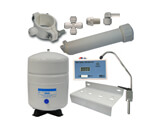
Residential Systems
Residential reverse osmosis systems need to take into consideration all of the parts described above. In addition, there are some other factors that require special attention in residential systems. Most of these concerns are due to an improper selection of some key components in the manufacturing of these systems.
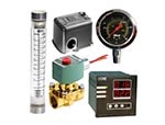
- Flow Restrictors: Poor quality flow restrictors may cause systems to run at higher recoveries resulting in shorter membrane life.
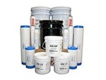
- Prefilters: Sediment and carbon filters used in the pretreatment of the residential systems must not shed fibers or release carbon fines.
- Check Valves: A faulty check valve can cause a back pressure on the permeate side of the membrane element resulting in a physical damage to the membrane.
Summary
Mistakes in the design and operation of reverse osmosis systems can be avoided by following the recommendations outlined in this paper. There are no short cuts in providing systems that give trouble free performance with a long useful membrane life.
Diagrams and References
Concentration Polarization
|

Recovery% Recovery = (Permeate ÷ Feed) × 100
Concentrate Concentration = (100 ÷ [100 - R]) × FC FC = Feed Concentration |

Feed FlowHigher Feed Flow Helps to Reduce Membrane Fouling. Example:
|


Request A Quote »
Contact us
for a quote or for any additional information
or call us at 1.800.321.9321